Click To Enlarge
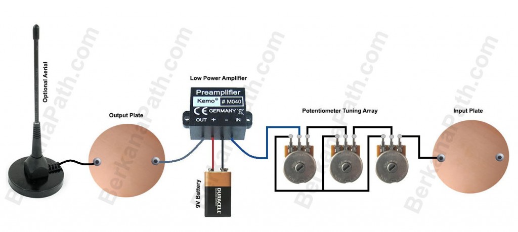
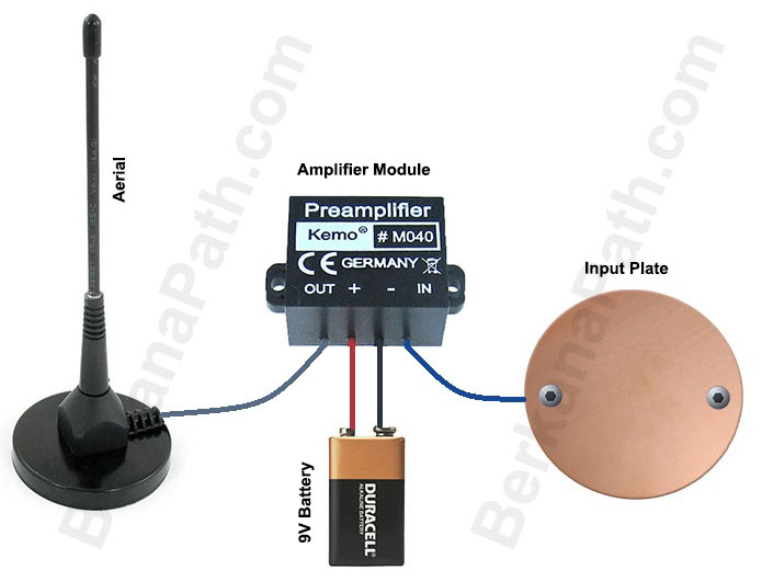
Here’s another simple schematic, based on my Super Simple Three Dial, and using the amplifier from the Wishing Machine posted yesterday. The Aerial is an optional extra, and is in no way necessary. You could experiment to see if it increases your output. As before most of this can be done with crocodile clips if you aren’t used to solder and soldering irons. I would add that it would be a good idea to secure and insulate the crocodile clips on the pins of the potentiometer, so that they are secure from pulling lose, and that the tips of the other leads don’t touch creating a short circuit.
It’s been a while since I last posted any schematics, so I thought I’d put together a schematic in my new simple style. The aim of these styles is that they are straightforward to follow, and fairly easy for anyone with no electronics background to get to grips with.
This is a simple wishing machine that uses a low power pre amplifier. I intend to do another drawing with a second stage amplifier for even more aetheric juice, but for now this is keeping it simple.
The input plate is where the written intention or wish is placed – I like to use sigils. The plate can be made of anything, but copper, brass and stainless steel work best. You could use a well instead, if you are really on a tight budget and want to experiment in true psionic style you could use a bean or coffee can, etc as your well. The only limit to what you can use, is that it has to be conductive.
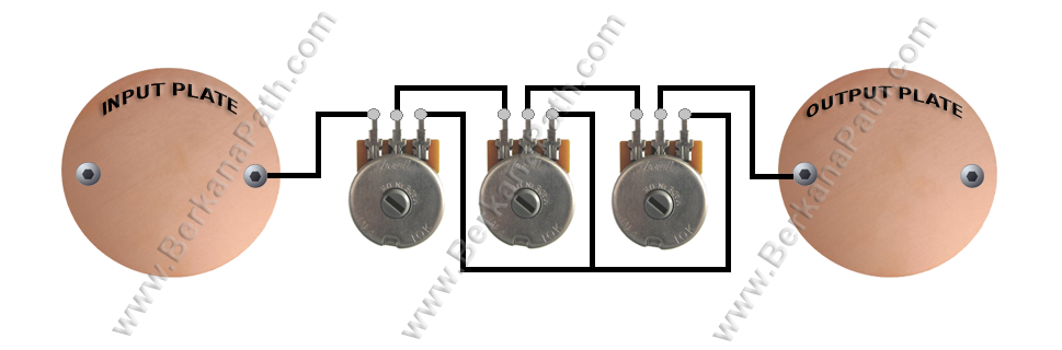
Presented here for your delectation is a super simple three dial radionics schematic. There is no techno jargon, or standard schematic imagery. The circuit is simple as shown. The black lines represent wires, and their connections. The bottom row of wiring simply shows that the last post on each potentiometer is connected to the last post on the next.
This type of circuit is also known within radionics as a passive resistance circuit. There are no coils, crystals, or amplifiers within this circuit, but that does not detract from its raw power. Generally, this circuit can be used to copy homeopathic remedies, or for imbuing a witnesses sample with a particular trend. For the latter, the witness sample would be placed on the output, and the trend would be placed on the input. The trend could take the form of a remedy, written or pictorial intention, etc. For use in agricultural radionics for instance; fertilizer, or pesticides could be placed on the input plate, and their rates dowsed for with a pendulum.
What you will need:
Once you have all your components you can begin to build to the above diagram. You should have chosen an enclosure/box which will allow you enough room to mount everything on one surface, usually the top. If it doesn’t, not to worry; some people will mount the plates on the top surface, and the dials on one of the sides to make more room.
It’s quite simple from here on in. Use your intuition, and build an instrument which you find visually and aesthetically appealing, as this will increase its potential. You are imbuing the device with your own power, use it wisely.
This information is free to copy and distribute. All I ask as my copyright condition is that you attribute the work back to BerkanaPath.com. These posts and diagrams take a great amount of work, and it is saddening when people abuse the work of others. This is why I am being forced to watermark all of my intellectual properties. Thank you for understanding.
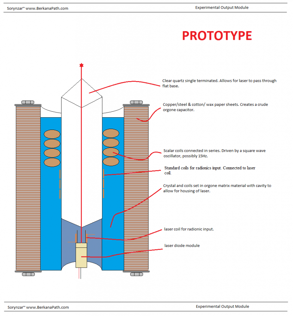
Here is a design I had lying around on my computer. The ultimate goal of the module was to have it cast into a resin block about 2ft tall, with a large clear quartz crystal embedded into it. The laser is used experimentally to allow for light transfer of a radionics signal, it could also be used to pulse audio frequency into the heart of the quartz. The orgone capacitor is used to collapse the gravity field around the regular orgone matrix. While it is a crude version, the orgone capacitor is far more superior to the orgone matrix material. The capacitor needs a lot of work, and it is something which I have begun to look at under the project title of Orgone Stacks. No working version of this experimental module has ever been put together, but it is something I would like to try, if time and resources allowed.
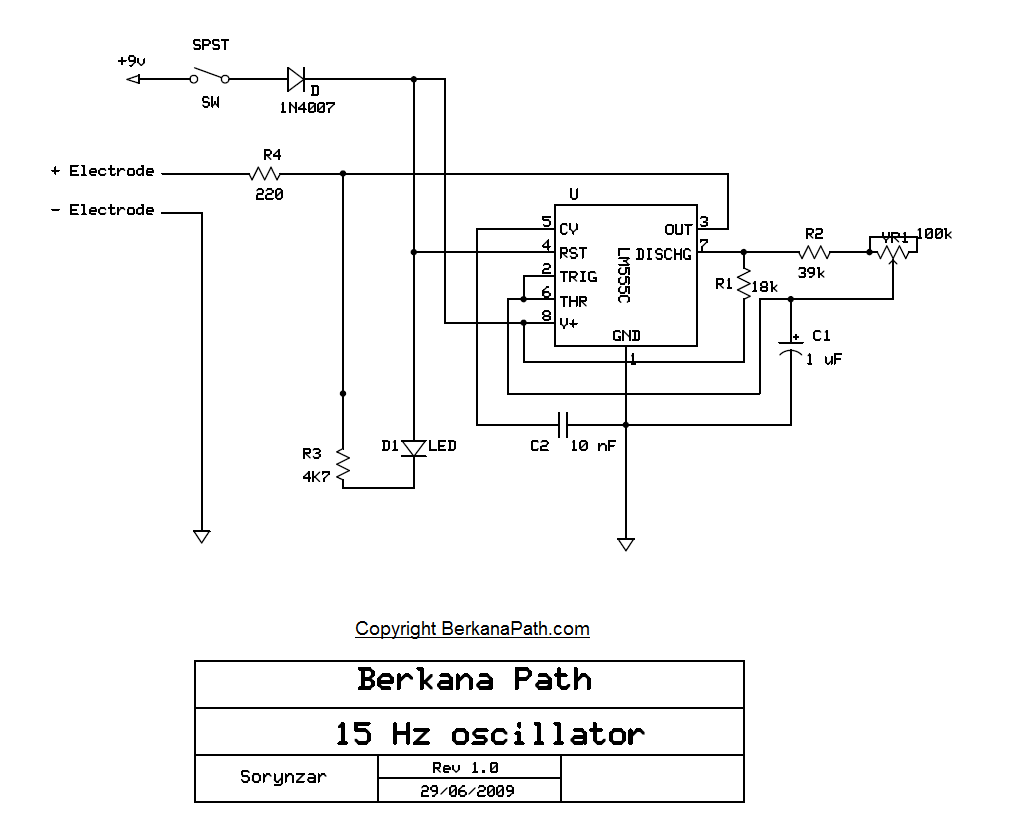
I have uploaded my own personal schematic of a 15Hz zapper circuit. I spent some time trying to find a good schematic to follow last year, but I discovered that most of them were flawed and the timing formulas did not equate their components to being the correct 15Hz output. To remedy this, I drew my own schematic, built the circuit on a breadboard and tested the output using an oscilloscope. (Yes I test my circuits, unlike some armchair engineers) It is quite difficult to get an analogue circuit dead on 15Hz due to the poor tolerance of the components. The best tolerance you can get for this particular circuit components are 1% for the resistors and 2% for the capacitors. All of this considering, I managed to get the zapper circuit tuned to 15.15Hz using the variable resistor. Without the tuning, the circuit could output anywhere from 12-20Hz.
While this circuit is labelled as a zapper circuit it does not necessarily need to be used for that purpose. I originally used this circuit to pulse a scalar coil. I found that the circuit output, while o.k for zapper functionality has a very low power output for use with a coil. To remedy this issue, I have recently redesigned the circuit with a small power amplifier included, which significantly boosts the output from the coil.
Some other things for you to consider when using the zappers are the electrodes themselves. Instead of using two hand held copper electrodes, why not create a true anode and cathode by having a Zinc and a copper electrode? The results are quite interesting.
To view a larger image of the schematic, just click on the image, and it will take you to the full size drawing.